Bendigo On Road Radio Control Car Club
powered by TidyHQGears
Gears
Am I geared up for this?
I’m new to this sport and not only am I coming to terms with learning to drive, I’m also all at sea with understanding the underlying principles of Final Drive Ratio (FDR) and Transmission Drive Ratio (TDR), the different sizes of spur and pinion gears, etc. The list goes on and on. I feel I need to be a practising physics professor before I touch the RC car on the track and squeeze the trigger. But I also enjoy learning and understanding things and thought it might be worthwhile adding a section to the website where these things can be shared, discussed and maybe even understood. If you’re interested! If so, here is a noob’s perspective on how our 1/10th scale on-road touring car transmissions work. And I’d be more than happy for anyone with experience and a better understanding than I, chimes in to correct me along the way.
What are you torqueing about?
I set out specifically to understand what impacts changing spur and pinion gears have on a car’s performance. This is the focus of this specific discussion. It won’t go in to car setup such as camber, toe, droop etc (which may be a follow-on topic as I learn about those too!) but will concentrate on the specifics relating to gearing and how to calculate theoretical top speeds based on different ratio settings. Here goes ….
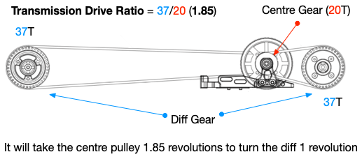
Transmission Drive Ratio (Internal gear ratio)
TDR is the ratio for how many revolutions it will take the centre gear (attached to the spur gear) to turn the differential pulley. I have a Destiny RX10-SR in the “stock” kit which comes with a 37T diff set containing 37 teeth. The Centre gear which connects to the differential pulley has 20 teeth. Effectively, this means the transmission ratio is 37/20 or 1.85.
This will vary between car makes and models. The Destiny RX10-SR for example comes in kits with a 38T and 40T differentials that alter the TDR to 1.9 and 2.0 respectively.
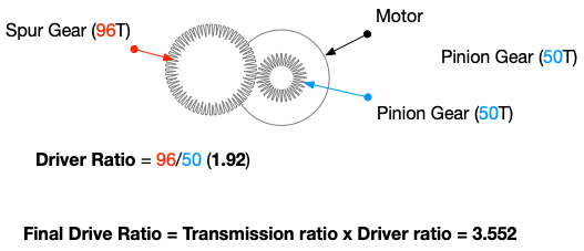
Pinion and Spurs (Driver gear ratio)
The pinion and spur gears collectively make up the driver gear ratio and the second half of the Final Drive Ratio equation listed below. It is calculated by dividing the number of teeth on the Spur gear by the number of teeth on the pinion gear. In the example diagram here, using a spur gear of 96 teeth (96T) and a pinion of 50T, the gear ratio is 1.92.
Final Drive Ratio (FDR)
FDR is calculated by multiplying the internal and driver gear ratios calculated above. They have a direct bearing on acceleration and top speed. In our Bendigo Spec Class competition, the ratio here has been set to 3.5 so all racers need to align a spur and pinion combination that directly aligns to this. It’s not common a ratio here is predetermined in racing classes as racers are usually free to determine a combination that meets their driving style or track conditions for acceleration and top speed.
Our Spec class however is designed for close competitive racing and by enforcing a FDR, it ensures all cars will have similar top speed and acceleration attributes.
Rollout
Rollout is the other attribute that can impact top speed. It is the measurement of how far the car will move forward for every turn of the motor. This is what we need to determine max speed calculations (to follow).
To calculate roll-out, we need to think all the way back to school maths and recall Pi; the calculation of a circle circumference. That value is 3.1415. Next, we need to know the tire diameter. New tires with no wear for my Destiny are 63mm.
Tire diameter * Pi (63 * 3.1415) = 197.9145
Spur / pinion x internal gear ratio (96/50 * 1.85) = 3.552 (or FDR)
Roll-out is the top value divided by the bottom value.
= 197.9145/3.552 = 55.72 mm per motor turn
So let’s now see what happens if the tires wear down 2 mm …
Tire diametre * Pi (61 * 3.1415) = 191.6315
Spur / pinion x internal gear ratio (96/50 * 1.85) = 3.552 (or FDR)
Roll-out = 191.63/3.552 = 53.95 mm per motor turn
This means a worn tire not only impacts traction, but also speed as the tyre diameter reduces and lessons the distance travelled for every turn on the motor. You can counter this by changing your spur/pinion gears but this will have other impacts as discussed below.
Putting it all together
So what do these values even mean? Changing this ratio through pinion / spur combinations impacts the power and top speed. A smaller tooth pinion gear will result in a higher FDR meaning the motor will turn the pinion more revolutions resulting in my torque and faster acceleration. Because the FDR is now higher though, the motor ends up needing to turn more times to turn the wheels due to the higher differential in the spur / pinion combination. So whilst increasing the FDR increases acceleration, it also decreases top speed.
Conversely, if you increase the pinion gear, you are making it closer in size to the spur and decreasing the FDR as a result. Just like riding a bike and trying to start out in a higher gear, it is more difficult to get started so acceleration is impacted. However, because the spur / pinion combination are more closely aligned, the motor does not have to work as hard and can attain a better top speed.
To summarise:
* Increasing tooth count on pinion or Decreasing the tooth count on spur will decrease FDR resulting in a decrease in acceleration but increase in top speed
* Decreasing tooth count on pinion or increasing the tooth count on spur will increase FDR resulting in an increase in acceleration but decrease in top speed
Experienced racers will alter the FDR based on track conditions for greater speed down long straights or for better acceleration for tracks with an emphasis on cornering.
How fast it will go?
Ok. So now we have our tyre diameter and all our ratios, we can work out our theoretical top speeds with one additional consideration; the motor. Motors are rated for a certain maximum Voltage which consequently limits the maximum RPM (Rounds Per Minute). With this in mind, here’s how we go about it.
Electric Motors are often rated with a KV number such as 2000 RPM/Volt DC. My Trinity 21T motor (2000KV) functions at 4.2V per cell (2 cells) which equates to 16800 revolutions per minute (4.2 * 2 * 2000 KV)
From this 16800 RPM value we divide it by the FDR (in this case 3.552). This value equates to how many times the wheels will turn in a minute; in this case 4730.
Next, we take the diameter of the tyre (63mm) and divide it by Pi (3.141), further divide it by 1000 (so we get the distance from millimetres to metres) and finally, multiple it by 60 to take the value from minutes to hours. This equates to:
0.63 / 3.141 / 1000 * 60 = 0.012
Finally, we take the 4730 * 0.012 and this is our kilometres per hour! 56kph
Let’s turn things up a notch and keep the same voltage, tyres and ratio’s but swap out the 21.5T motor for a 13.5T.
13.5T 3000 KV motor would be:
4.2 * 2 * 3000 KV = 25,200 RPM
25200 / 3.552 (same FDR) = 7094
7094 * 0.012 = 85kph theoretical maximum.
If all of that does your head in, there are some great gear ratio apps on the Google Play and Apple IOS stores that does all of this for you. I found that until I understood the concepts here, I struggled to even know what the apps were referring to for input values. So manually doing this here helped me in understanding the apps for future and easy calculations.
The Summary
The irony for me is that this is all theoretical and doesn’t actually impact me as someone still learning to steer the damn thing around a track without crashing and braking parts. But what I have taken away from this is that there are so many ways to change things that it is daunting to know what changes where, would be the best place to start. In relation to the gearing considerations above, it can be simplified to lowering the FDR for tracks with long straights where you want speed over acceleration or increasing the FDR for tracks where you want greater acceleration out of corners on winding tracks.
I’ve found the exercise in trying to understand this and documenting it beneficial to me and I hope you take some value out of it as well.
